Engine Rebuild 4: Re-assembly - Top End.
Although this section of the Engine Rebuild Guide is the final part of a series of procedures, it can also be used "stand-alone" as a step-by-step top end assembly procedure. Refer to the beginning of Section 2: Stripdown for tips on disassembling the top end.
The procedure of re-assembling the top end is the same for all NSR models, MC16 through to MC28. Indeed, the procedure is virtually identical to that of any modern liquid cooled 250 2-stroke.
In the first part of this series, each barrel and head was removed as an assembly. This was to demonstrate the fact that unless it is absolutely necessary (i.e. blown head gasket/combustion chamber reprofiling), there is no need to separate the two components. The following steps though, show re-assembly of the top end including fitting a new head gasket and replacing the head to provid a more comprehensive procedure.
|
 |
| NOTE: | The head gasket should always be fitted "dry". |
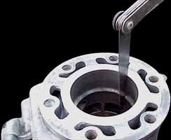
If the head and/or barrel surface shows only minor signs of scoring, then they can be "lapped". Best results are obtained by lapping both components, but it is not entirely necessary. Source a piece of sheet glass approximately 300x300mm and 5-8mm thick - the thicker, the better. You will probably be able to obtain an "off-cut" from a local glazier. Apply a small amount of FINE valve grinding paste (available from any good auto store) to the centre of the glass sheet and a little light oil. With a little light pressure, in a circular motion, rub the head/barrel until there is a uniform light grey appearance across the entire surface. For best results, lapping the head and the barrel together will produce a perfect edge between the two components.
| NOTE: | All traces of grinding past MUST be rinsed from the |
| components before re-assembly. Failure to do so may cause catastrophe inside your freshly built motor! |
Pack rag around the con-rod in the crankcase opening to prevent anything (i.e. circlips) falling into the bottom end.
Closely inspect each barrel for any signs of cracks around the studs and ports, particularly the exhaust port. Failure is not common in these areas, but should be checked never-the-less. (An RC Valve overhaul procedure will follow soon - watch this space!) Give the combustion chamber a light clean with a piece of Scotchbrite![]() . If a good high quality 2-stroke oil has been used, cleaning of the components will be considerably easier and quicker! Finally, ensure the RC Valve assembly is clean of carbon deposits and operating freely.
. If a good high quality 2-stroke oil has been used, cleaning of the components will be considerably easier and quicker! Finally, ensure the RC Valve assembly is clean of carbon deposits and operating freely.
Piston rings now share a common part number (13010-KV3-305), right across the model range. Before fitting the rings to the pistons, the "installed ring gap" should should be measured. To do this, place a piston ring (dry) in the top of the cylinder, then use a piston to push the ring squarely down the bore, approximately 30mm. With a feeler gauge, measure the space between the two ends of the ring.
| The end gap for each ring should be: | MC16 | 0.23 - 0.38mm | Service limit 0.43mm |
| MC18 J | No data available | ||
| MC18 K | No data available | ||
| MC21 | 0.30 - 0.45mm | Service limit 0.50mm | |
| MC28 | 0.30 - 0.45mm | Service limit 0.50mm |
If any of the ring gaps are tight, then there is a risk of seizure as the ring expands when it reaches operating temperature. With a fine diamond file, gently relieve the ends of the piston ring until it is at the correct tolerance. Make sure the file is kept square to the end of the ring to prevent a false reading with the feeler gauge.
Fit the new piston rings to the pistons, noting the top ring is a "keystone" design. The stock MC16 setup uses an "expander" ring under the bottom ring, but this is no longer catered for - just omit them from the rebuild or use the old expanders if you wish. Each ring also has an I.D. mark; the rings should be fitted so the I.D. marks are facing upwards. Finally, ensure the ring gaps are aligned with their locating pegs in the piston grooves.
Fit the first gudgeon (wrist) pin retaining circlip into its' groove in the piston, ensuring that it is seated firmly. Install the circlip with its' gap at the very bottom of the groove. Very lightly oil the gudgeon pin with the same 2-stroke engine oil you will run the motor on, and press it part way into the piston. If it is a tight fit then gently warm the piston with a decorators' heat gun or by soaking a cloth in hot water and wrapping it round the piston for a few moments. Oil the small-end bearing with more 2-stroke oil and place it in the small-end of the con-rod. Ensure the "IN" mark on the top of the piston is facing the INlet side of the crankcase and push the gudgeon pin through the small end bearing until it is firmly seated against the first circlip. Fit the second circlip, again with its' gap facing toward the bottom of the piston. Now remove the packing from the crankcase.
| NOTE: | Always use NEW circlips. |
| NOTE: | If re-using pistons and the IN mark is not viewable, then |
| the ring gaps are on the inlet side of the piston. |
Inspect the crankcase/barrel mating surfaces for any signs of damage and/or remains of gasket. Only use a dedicated gasket scraper to remove gaskets, never a pointed object such as a screwdriver! Work on one cylinder at a time; fit a new base gasket. If disassembly has been done carefully, and the mating surfaces are in good condition, then fit the gasket dry. This will ease later disassembly for the next overhaul.
| Note: | If instant gasket is required, then use the most minimal |
| amount possible to give an even coverage. |
Rotate the crank so the piston is at top dead centre (T.D.C.). Oil the piston and rings with 2-stroke oil, and also apply a light, even coat of 2-stroke oil to the cylinder walls. Using your hand to compress the piston rings, ease the barrel down over the piston.
| NOTE: | Avoid excessively twisting the barrel as the ends of the |
| rings could pop out into a port! |
Once the piston is about half way into the barrel and the rings are protected, it is safe to lower the barrel all the way on to the crankcase. Manipulate the crank by rotating the flywheel or clutch assembly to aid locating the barrel into position. Fit the 4 cylinder retaining nuts "finger tight". Tighten the 4 nuts evenly and in a diagonal sequence, to a torque of 2.5kg-m.
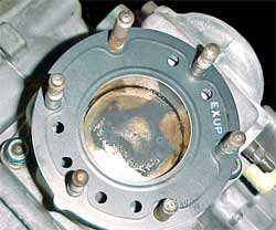
Fit the new head gasket to the cylinder with the marking EXUP visible and above the exhaust port as shown in the photo.
Lower the head into position and fit the 6 retaining nuts finger tight. Tighten them in 2 or 3 stages to a torque of 2.2kg-m, again working diagonally to ensure the head is tightened down evenly. Set the gap on a new spark (MC16: NGK B9ECS/B9ES, MC18/21/28 NGK BR9ECM) to 0.7 - 0.8mm, screw the plug into its' hole and tighten it to a torque of 1.5 - 2kg-m.
Assuming the motor is already installed into the frame, refit the RC Valve pulleys and cables, and adjust the valves as outlined at the end of the 250 Engine Tuning section.
![]()

![]()