NSR-WORLD.COM

NSR-WORLD.COM
All NSR250Rs leave the factory with only a stifled 40-45hp. However, it was always destined by it's designers to be so much more!
Each model is restricted in some way*, but can be tuned with a varying degree of both difficulty and success.
*The standard ’87 MC16 & ’88 ignitions are not lmited by the factory.
In 1988, Honda commissioned NGK to produce an 11mm shorter [BR9ECM] spark plug for the NSR250R MC18 R2/4J to increase clearance for the front wheel.

For the HRC TT-FIII NH3 models, the NGK Racing R5300A plugs were employed. These can be used on standard bikes too, and one is indeed recommended for the MC21 and MC28 when performing the [NKD] HRC head conversion, as outlined in the Engine Tuning section. While R5300A-10 is called for in the NH3 and NKD kit manuals, a 9.5 plug is more suited to street use.
Due to the cost of the R5300A and the special silicone cap required, we only recommend its use on the lower cylinder. There is no significant or even measurable difference over the BR9ECM for street use.
For more model-specific information about ignition delimiting, see the following section for your particular NSR250R.
1987 NSR250R MC16
The NSR250R MC16 is the anomaly in the ignition tuning department, as it's the only model without any electronic restrictons.
While the HRC TT-FIII NSR250RK is rated at 65hp, it utlises a fully adjustable RS250R NF5A ignition, which is largely impractical for most use cases. The SP specification however, utilises the standard bike's twin CDIs.
The MC16 limitations (limitations, not restrictions) are hard-coded into the CDIs and RC Valve controller, and its 45hp is more a consequence of early 80s design limitations than legislation. The 1987 SP race specification utilised the stock ignition system, and was good for 60hp.
Therefore, to push past the MC16’s CDI limitations there are only two realistic options for ugrading the electronics.
- Retrofit the PGM-I or PGM-II ignition components from the ’88 or ’89 MC18 respectively. However, this isn’t a simple bolt-on upgrade. The wiring harness, PGM-I, and matching RC Valve controller/RC Servo from the MC18R2/4J is the simpler of upgrades, but with either PGM upgrade, great care has to be taken with the operation of the RC Valves. Not only are the shape and size different between the MC16 and MC18 RC Valve flaps, but the cables differ, as does the sweep of the servo, and consequently the rotation of valve flaps themselves. If poorly adjusted, strain on the servo will cause internal damage to the PGM within seconds.
- An aftermarket programmable CDI by either Zeeltronic or Ignitech. Neither are very common on the MC16 though, but both can do a great job fine tuning both the ignition curve and RC Valve operation.
1987 NH3 "TT-FIII" spec
The NSR250R MC16 TT-F-III NH3 “RK” [Race Kit] setup utilises RS250R NF5A ignition components. The special NH3 crankcases are machined to accept the small flywheel and accompanying stator & pulser coils of the RS, and can be easily identified by the blank [untapped] standard pulser coil bosses. Standard MC16 cases can be machined to accepet the RS250R components, but NF5 parts are becoming increasingly rare and expensive.
The MC16 is increasing in popularity over recent years, not least because of the soaring cost of the later models. Why not drop on over to our NSR250R Forums and start a discussion about your MC16 and your plans for it?!

1988 NSR250R MC18 R2/4J
The NSR250R MC18 R2/4J is the simplest of all the models to delimit. The PGM-I isn't actually limited, but the RC Valve operation is restricted.
Speed restriction became law in Japan in 1988, and the MC18 R2/4J was the first model to be artifically limited to 45hp and 180kmh.
MC18 MkI’s [R2J & R4J] were speed restricted by limiting the opening of the RC Valve and its final drive gearing, which are very simple restrictions easily bypassed! Not only is derestriction on these bikes free, but once completed, there will be a horse-power gain too! What more could you want?!
There are two different wiring harnesses for the 1988 NSR250R. The earlier harness has an RC Valve “sub controller” unit and a 6-pin red connector that you need to locate under the rear seat pad.
The later versions don’t have the sub-controller, and have a white 3-pin connector, in a similar position. Next to each of these connectors is bullet connector fed by a black/blue wire.

1988 "SP" race spec
To delimit either of the MC18R2J/R4J RC Valve operation, remove the seat unit and locate the red or white connector near the tail light (early version shown in the above image).
Look for the individual black/blue wire with the “bullet” type connection. Pull the connector apart and tape up the male end to prevent it shorting on the seat subframe and you’re done! Like we said – simple!!
Now, instead of of the motor falling flat at 10,000rpm (despite how carefully you have set the RC Valves up!), it will pull right through to the red in every gear! A little careful jetting and maybe a change of final drive ratio should see top speed increased to a little over 120mph and power up around the 60hp mark!!
This is the official HRC “SP” race series specification, where only a standard ECU is permitted for competition.
Info
Ensure the correct bullet connector is disconnected, as demonstrated in the HRC video! Do not disconnect the black/blue wire at the RC Servo end of the harness.
CAUTION
It is imperative the jetting is checked and optimised once the ignition is delimited.
1988 NH3 "TT-FIII" spec
As with the 1987 MC16 RK, the 1988 MC18-I RK utilised an RS250R NF5 derived analogue Kokusan Denki ignition.
The image shows standard MC16E crankcases that have been modified to accept the NF5 stator.

1989 NSR250R MC18 R5/6K
The 1989 NSR250R MC18 R5K/R6K was the first model to have a restricted ECU.
The PGM-II is restricted by grounding the infamous Honda orange/blue wire! This system is used on countless JDM Honda models, and even some world market models. (Other notable cases are the RVF750 RC45* and the NR750.)
To delimit the MC18 R5/6K PGM-II, locate the orange/blue wire coming out of the PGM-II unit, and splice it into the black/white wire as per the following ’90-’93 MC21 section.

The above dynographs show an MC18 R5K in various states of tune..
- The Green trace (45.2hp) illustrates a completely stock bike as a base-line to assess modifications against.
- The purple trace (61.3) shows what can be attained with nothing more than the wiring modification and some careful jetting – some 15 horsepower!
- The blue trace (61.7hp) sees the bike equipped with race cans, a modified airbox, and some more jetting changes to account for the increased gas-flow.
- The final run is shown by the red trace (63.2hp) and shows the difference between race pipes and stock pipes.*
Although the stock MC18’s expansion chambers are very good (Honda saw fit to only make them quiet, and not restrict them very much) the race pipes add 1.5hp at the top-end and also 500rpm of healthy over-rev. This is great on the track or down the pub, but the stock pipes really score heavily over the race pipes in the mid-range, producing around an extra 9hp more than the race pipes at 8000rpm!
Note:
Follow the step-by-step guide in the following ’90-’93 MC21 section to delimit the 1989 NSR250R MC18 ignition.
WARNING!
Ensure you connect the O/Bu wire FROM the PGM (16P black connector side) to 12V.
DO NOT connect the main harness side of the O/Bu to 12V.
*RVF750 RC45 delimiting information can be found on our sister site Force-V4.com »
1989 MC18 NKD "SP" spec
An HRC “SP” delimiter kit is available for the 1989 R5/6K models, which will convert a standard wiring harness and PGM-II to full power.

CAUTION
Delimiting and derestriction are not the same thing!
Our wire splice is all that’s needed to delimit the PGM-II, however, derestriction isn’t simply a case of performing the wire splice.
It is essential that the jetting is checked and adjusted when delimiting the ignition, irrespective of the method used.
'90-'93 NSR250R MC21
The NSR250R MC21 is restricted in 4th, 5th and 6th gear by programmed maps in the PGM-III, activated by a GPS (gear position sensor). This detects the top three gears and when the road speed reaches 180kph (112mph), limits the ignition advance and RC Valve position, causing the power to tail off.
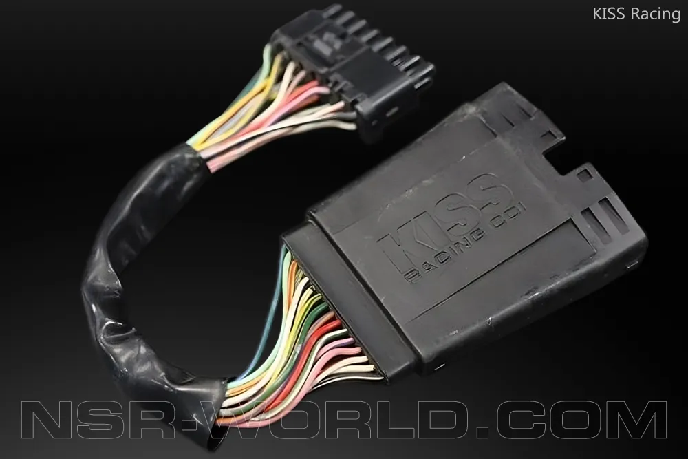
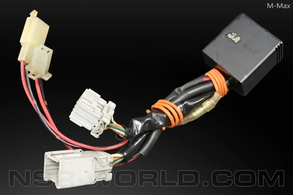
There are many makes of speed derestrictor on the market for the MC21, the most common at the time were manufactured by KISS Racing and M-Max, and can still often be found for sale on various auction sites.
The KISS Racing delimiter simply plugs inline between the standard harness and PGM-III’s black socket, and is the simplest, easily reversible solution. A “wire-splice in a box”.
The M-Max box connects inline of the power feed to the rear brake switch and G.P.S. connector, but still necessitates cutting and splicing into the orange/blue wire. M-Max claims to disable the speed sensor and allow the PGM-III to provide the optimum setting, but in reality it’s all smoke and mirrors! The M-Max delimiter is nothing more than an expensive wiresplice, and the G.P.S. wires do nothing more than loop around inside the plastic casing!
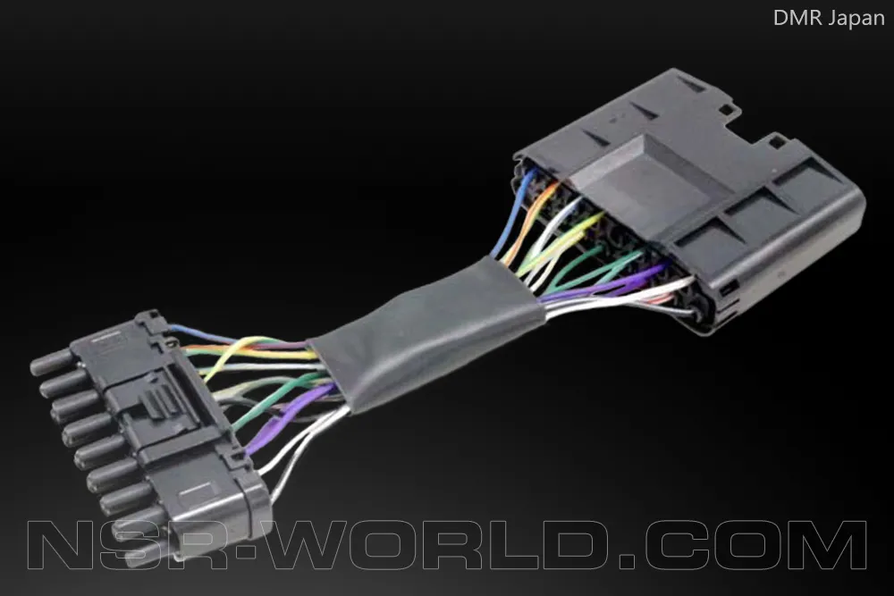
New to the market is a delimiter produced by DMR Japan, although this unit is untested by NSR-WORLD.COM. DMR are however, renowned for manufacturing high quality aftermarket parts for a range of Honda models.
'90-'93 MC21 Wire Splice
Info
The MC21 wire-splice procedure can also be used to delimit the MC18 R5/6K PGM-II.
To gain full OEM power on the MC21, for free, the “wire splice” needs to be performed. This disables the ignition limiter in 4th, 5th, and 6th gear. Although a stock NSR will rev in these higher gears, the restricted ignition prevents it from making any useable power and therefore acts as an electronic speed limiter. The offending wire in this restriction is the ‘legendry’ orange and blue (O/Bu) wire! In the OEM configuration it is routed to earth (ground), but to delimit the ignition it needs to be powered by 12V.
- Ensure the ignition is off, and disconnect the battery.
- Unplug the black and white connectors from the PGM-III and remove the insulation from the black connector to expose as much wire as possible.
- Separate the orange/blue (O/Bu) and black/white (Bk/W) wires from the rest.

- Snip the O/Bu wire approximately 70mm from the black connector, and on the connector side, remove 5mm of insulation to expose the copper core inside.
- At the same distance from the connector, remove 8mm of insulation from the Bk/W wire.

Note
Do not cut the Bk/W wire, only remove its insulation.
WARNING!
Ensure you connect the O/Bu wire FROM the PGM (16P black connector side) to 12V.
DO NOT connect the main harness side of the O/Bu to 12V.
- Solder the O/Bu wire to the Bk/W wire. Use plenty of soldering flux to ensure a perfect connection.

- Insulate the soldered connection, and also the bare end of the snipped O/Bu wire with insulation tape or better still, heatshrink.

1990 MC21 NH3 "TT-FIII" Spec
HRC produced the most comprehensive Formula 3 kit ever for the 1990 MC21, and for the first time used a unique NH3 digital PGM-II ECU over the previous model’s Kokusan Denki analogue RS250R NF5 units.
Once again, a lightweight flywheel and adjustable stator plate were employed on the NH3, but unlike the dedicated PGM-II, were again RS250R NF5 items.

'91-'93 MC21 NKD "SS/SP" Spec
HRC produced a race wiring harness and additional RC Valve sub-controller [30490-NKD-840] from 1991 for the SS/SP race classes. The sub-controller will only plug into an HRC race harness. Although the harness and delimiter are now discontinued, NOS (new old stock) can still be found online from various outlets, but the cost these days is soaring!
Naturally, the HRC race harness has no provision for any of the street equipment or oil pump.

Note
While the grey connectors can be cut off the HRC sub-controller, and it be spliced into the standard wiring harness, it actually does nothing more than our earlier documented wire-splice.
The HRC sub-controller clearly states “NOT FOR HIGHWAY USE” on the casing, whereas our wire-splice is an “invisible” modification.
CAUTION
Delimiting and derestriction are not the same thing!
Our wire splice is all that’s needed to delimit the PGM-III, however, derestriction isn’t simply a case of performing the wire splice.
It is essential that the jetting is checked and adjusted when delimiting the ignition, irrespective of the method used.
'94-'96 NSR250R MC28
The NSR250R MC28 is by far the most complicated and costly model to delimit.
A common misconception in the early days was that you could simply insert an HRC "smart card" into the PGM-IV and override the limitations. Unfortunately this couldn't be further from the truth.
To utilise the HRC cards as Honda intended requires the replacement of the standard wiring harness with an HRC equivalent. Unfortunately, this disables all of the features of the PGM-IV that are no longer required for track use. The odometer, oil/ignition warning light, and neutral light no longer work, and the LCD turns into a big temperature gauge. The HRC harness also eliminates the oil pump solenoid connection, and has no provision for lights, indicators (turn signals) and horn etc.
However, there is a “wire-splice” modification that allows the use of the HRC cards with a stock harness. You still lose functionality of the street instrumentation and warning lights though.

NSR250R MC28 Wire Splice
- Unplug the black and white connectors from the PGM-IV and remove the insulation from the black connector to expose as much wire as possible.

- Now separate the following wires from the rest: Green (earth), Light Green/Red (neutral switch), Green/Pink (oil level indicator), Green/White (side stand switch).

- Snip the LtGn/R, Gn/P & Gn/W wires approximately 60mm from the black connector, and remove 5mm of insulation to expose the copper wires inside.
- At the same distance from the connector, remove 5~10mm of insulation from the solid green earth wire.

Note
Do not cut the Green wire, only remove its insulation.
- Solder the three snipped wires to the green (earth) wire. Use plenty of soldering flux to ensure a perfect connection.

- Insulate the soldered connection, and also the bare ends of the snipped wires with insulation tape or better still, heatshrink.
- Plug everything back together, and the job is done.

CAUTION
The MC28 wire-splice mod allows both standard and HRC cards to be used, however the jetting requirements for STD vs. HRC cards differ significantly, and it is strongly advised to only use the specific card that the setup is adjusted for.