NSR-WORLD.COM

NSR-WORLD.COM
All NSR models share the same engine configuration; A crankcase inducted 90° V2, with a bore & stroke of 54.0 x 54.4.
This configuration is designated MC16E and appears on the crankcases of all models, regardless of age. Do not panic if you find the prefix MC16E on your MC28 engine cases!
Out-of-the-box, the NSR250R motor is extremely capable, as a direct result of it's Grand Prix heritage.
Not only are the RS250R NF5 crankcases derived from the NSR250R cases, but the MC16E crankcases are themselves directly descendant of the 1985 world championship winning RS250RW [NSR250] NV1A.

1986 NSR250R MC16 power unit with RC Valve.

1987 RS250R NF5A power unit with ATAC.
There is a slight rise in compression ratio throughout the years, and subtle changes to the exhaust port and RC Valve shape, but unlike its contemporaries, the overall NSR250R engine layout remained the same throughout its entire lifespan.
In 1989 the crankshaft was redesigned with a centre seal integrated into the centre main bearing, and 1990 saw a swap from hexagonal shaped barrels to more conventional round ones, increasing both strength and cooling efficiency. The crankshaft was also further refined and strengthened in 1990.
Year-on-year the crankcase internals and inlets were progressively cleaned up and refined, with the MC16 of course being the least refined, but on the whole, all models are actually capable of high 50s RWHP without modification, with the MC21 and MC28* capable of low 60s. With a little internal crankcase modification a noticeable increase in power can be realised, with in excess of 65rwhp readily available for the MC21.
*MC28 requires aftermarket silencers and exhaust modification to see over 60hp.
The follow are basic guides for reliable "street" tuning, designed to help liberate easily available horsepower. More in-depth tuning information will be made available later in a series of Formula 3 biased pages.
Cylinders
The overall layout of the motor is very similar to the '87-'92 RS250R [NF5], although RC Valve wasn't implemented on the NF5 until 1988.
In fact the [’87-’92] NF5 motor will bolt straight into the 1986 NSR250R MC16’s frame using the standard [solid] mounting points, however, from 1988 the NSR250R uses flexible [rubberised] engine mounts, so while the motor will fit, modification is required.
A number of NF5 parts are interchangeable with the NSR’s, but this will be covered at a later date in the aforementioned F3 pages.

Typical 1990 NSR250R MC21 SP mass-produced barrel irregularities.
The porting, both in port shape and timing, although very similar to the RS, is Honda’s best compromise between performance, tractability, and reliability. The barrels can be ported to NF5 specification, but some components will undoubtedly suffer some longevity, and isn’t recommended for the majority of use cases. Generally, the best improvements to make are by optimising the current configuration.
Although the port layout from the factory is already very good, both in terms of tune and finish, stock barrels can benefit greatly by some attention.
NOTE:
The following information regarding the barrels and porting is applicable to all models. However, with regards to the MC21 and MC28, use and modification of SE/SP barrels is recommended.
The MC18 SP barrels and heads do not differ to the R models, but the MC21 and MC28 SE/SP barrels, heads, and RC Valves all differ to the base R models.
Using the above diagram of a typical mass production barrel, flaws in the layout can be clearly seen. The worst areas are the front transfer ports, closest to the exhaust port. One has a 3.5mm gap between it and the exhaust port, the other 4.5mm. The exhaust ports themselves and the bridge (the narrow strip between the two exhaust ports) is also generally a bad area, but is not something that can be easily shown on a diagram such as this. This particular barrel had a bridge ranging from 4.8mm to 5.5mm, depending on where it was measured!
Transfer ports
To start, each port will benefit from a general clean up. The floor of some of the ports can be particularly uneven, and each should be matched to its opposite number in the layout. This is very important for even distribution of fuel mixture across the piston crown to assure an even burn. Grind each port to the dimensions of the larger of its opposite counterpart. Widening the ports to match each other, within reason, will be OK, but try to steer clear of grinding the top or bottom as this will effect the timing and could easily ruin the barrel, just grind the bare minimum to even them up and square them off.
Ensure to maintain a nice radius in the corners, and chamfer all the edges, particularly the top and bottom edges to prevent the rings from snagging.

Significantly raising the roof of the ports (or lowering them) is best left to a professional tuner unless you are fully confident in your skills or are working on spare barrels as an experiment!
Equalising the dimensions of all the ports like this will have a marked, positive effect on efficiency, and increased efficiency is what tuning is all about. Although 0.2mm here and 0.5mm there doesn’t sound like much, very pleasing results can be obtained.
Another area that can often be improved is where the barrels meet the crankcase. Matching the two can greatly improve both flow and velocity, both essential to filling the combustion chamber. Matching the barrels to the cases is a slightly trickier job than just equalising the ports so will be covered at a later date, once we have the method documented.
To finish of the transfer ports, polish out any imperfections in the walls, and bevel off any sharp edges that the piston rings could get caught on.
Exhaust ports
Before working on the exhaust port, the RC Valve should be removed. This is by no means an easy job, as odds are the assembly has never been apart before and is “coked” up. Once the pulley hardware is removed, the spindle is simply a press fit; the circlip below the oil seal does not hold the spindle in place. Difficulty in extracting it is purely down to carbon deposits. Copious amounts of carb cleaning spray can help loosen a stubborn valve.
Irregularities in the exhaust ports are usually the most apparent. The bridge is often quite uneven and the barrel the measurements in the earlier diagram were taken from had a width ranging from 6mm down to 4.5mm in places. Cleaning the exhaust port up is an area where the greatest gains can be made.

The bridge can be safely narrowed down to 4mm, with 3mm being the absolute minimum width for reliability. Reducing the bridge this far is a job for a professional tuner though as it can cause it to expand under extreme conditions and pinch the piston causing seizure. A very narrow bridge is also susceptable to cracking if not warmed up steadily and allowed to cool properly.
Make sure both the roof and base of each port is again level, but it is not recommended raising the top of the port any further than 27.8mm, the measurement used for the RS250. Finally make sure once again the walls are smoothly flowed. Do not grind the expansion chamber side, although enlarging the outlet side of the port can produce significant gains, this again is best left to a professional as the removal of too much metal here will ruin the barrel.
RC Valve
The last job is to optimise the RC Valve. Setting up of the RC Valve is crucial to peak performance of the NSR250R, and is covered later.
After optimising the ports, and vigorously cleaning the barrel and RC Valve components, reassemble them. DO NOT use any form of abrasive paper on the power valve spindle, only clean it with a solvent, and if you must scrape it, use a only a blunt edge that won’t mar the shaft in any way.
You should find all the parts go back together very easily, and now they are clean and free, remove them periodically for cleaning!

It is highly probable that the RC Valve will need reshaping, so once installed check it. Open the valve so the highest side is flush with the top edge of the exhaust port. The lower side then needs to be ground so it too sits flush to the exhaust port. 0.5mm could be ground off of one side on the example barrel. HRC express considerable emphasis on correct setting of the RC Valve on the RS motors, something that the NSR will benefit from too.
Ultimately, equalisation and symmetry is what you are looking for in all of the ports. The stock layout from 1988 is actually very good, and for most applications doesn't need to be overly modified.
Supplementary modifications
In addition to optimising the barrels, the following simple modifications can help bring out the best in a lightly modified NSR250R.
HRC Head Conversion
The MC21 and MC28 HRC SS/SP [NKD] race specification calls for the replacement of the stock lower cylinder head with a second top head.
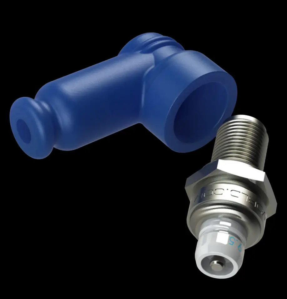
The stock NSR’s lower head has an offset spark plug position, consequently producing an inefficient ‘flame path’. Replacing the lower head with an upper one gives the plug a more central spark plug location, but you will run into clearance issues between the plug cap and the bodywork/front wheel, and therefore need to run a short RS250R NF5 style plug and cap.
HRC specifies a #10 spark plug [HRC: 31930-ND5-003 / NGK: R5300A10], however for street use NSR-WORLD.COM recommends a #9.5 plug [NGK: R5300A95]. A special silicone cap to suit the short plug must also be used. [HRC: 30700-ND5-751 / NGK: TRS1408F-B]
A race kit coolant hose [HRC: 19509-NKD-980] or equivalent is required to plumb the top head to the thermostat housing.

Info:
The HRC “NKD” kit is simply a stock SP top head and different radiator hose.
Special heads were produced by HRC for all other models, with the 1988 and 1989 MC18’s having true centre mounted plugs.
The following is a translated version of an official 1994 HRC bulletin for NKD SS/SP cylinder/head usage.*
The diagram illustrates the difference between SE/SP (L) cylinders/heads and R (H) cylinders/heads.
“The height difference of the cylinder and cylinder head is approximately 0.2mm. Therefore with a combination of the H cylinder and L head the difference becomes 0.4mm, approximately -0.8cc combustion chamber volume. (STD. ratio)
If using the L head with the H barrel, the compression becomes too high, and the possibility of frequent detonation will occur.”

*Some original text/translation may be altered or omitted for ease of understanding.
CAUTION!
The stock MC21 and MC28 run an already highly optimised compression ratio, and it is strongly recommended NOT to try and increase it any further.
When performing the HRC head conversion, NSR-WORLD.COM always recommends the use of an HRC 0.6mm base gasket [HRC: 12193-NFS-750] on the lower cylinder for street use, and the use of 97RON [min.] Super Unleaded fuel.
The stock MC21 and MC28 run an already highly optimised compression ratio, and it is strongly recommended NOT to try and increase it any further.
When performing the HRC head conversion,
NSR-WORLD.COM always recommends the use of an HRC 0.6mm base gasket [HRC: 12193-NFS-750] on the lower cylinder for street use, and the use of 97RON [min.] Super Unleaded fuel.

'90-'96 MC21/28 R and SP heads.
'90-'96 MC21/28
R and SP heads.
As already mentioned, the stock NSR250R compression is on the edge; particularly the MC21 and MC28 models. The KV3L “SP model” head [closest] in the image already shows minor signs of detonation, despite being taken from a completely stock bike.
Note the more pronounced 0.2mm recessed combustion chamber of the KV3H “R” head, to be used with the shorter [wet clutch type] barrels.
Info:
’90-’96 SE/SP barrels & heads are a direct fit to the R model [wet clutch] motors, with no further modifications required.
No increase in performance will be realised by exchanging R barrels & heads for SP items, however the SP parts are preferable when tuning.
Clutch
Often overlooked, the clutch plays an extremely important role transmitting the drive from the engine to the rear wheel. Upgrading it is a simple task! The obvious upgrade for an R model is to exchange the whole ‘wet’ assembly for a dry clutch from an SE or SP*.
For the SE/SP models, an even more simple upgrade is available! Simply exchange the innermost [2mm] steel plate (part 10) with a 2.9mm plate (part 9) as used throughout the rest of the assembly. Using the thicker plate effectively preloads the clutch springs, raising their ‘rate’ in the same way adjusting preload does on suspension. HRC has not specified uprated clutch springs since the F3 MC18 and many race bikes still use stock springs. However, EBC list uprated springs if you still feel they are required.

Although NSR-WORLD.COM has used both Jha and EBC springs in the past, the Jha variants are preferred as the EBC gave a noticeably heavier action at the lever. Naturally, the Jha parts are no longer available new, but NOS packs sometimes come up for sale on Yahoo! Auctions.
Some riders and racers to prefer the ‘feel’ of a wet clutch to a dry one, this is entirely personal preference, however, in our opinion the dry clutch is a better system. The benefit of the dry clutch is the ease of changing worn components without the need to drain the transmission oil, and as the plates wear, the resulting debris does not contaminate the oil either.
Note:
Be aware that the dry clutch setup is a full 1kg heavier than that of the wet clutch.
RC Valve adjustment
As mentioned before, setting of the RC Valve is absolutely crucial to peak performance of the NSR, and a valve too far open can be as disruptive as one not open enough!
Follow these simple steps to adjust them:
1987 MC16
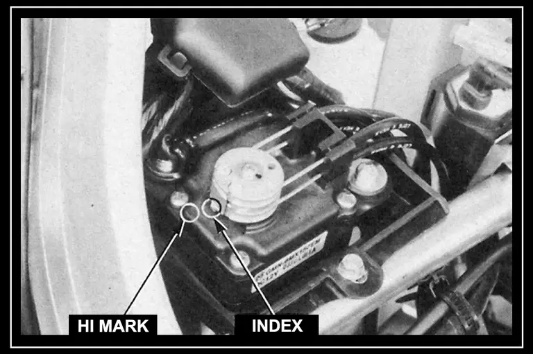
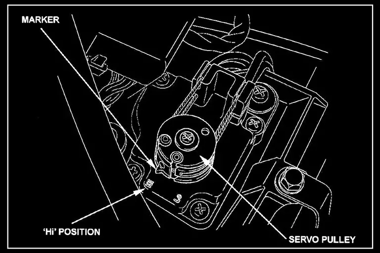
Start the engine, and slowly increase the engine speed. At approximately 2000rpm the RC Servo pulley will rotate to the “HI” position. Stop the engine with the kill switch.
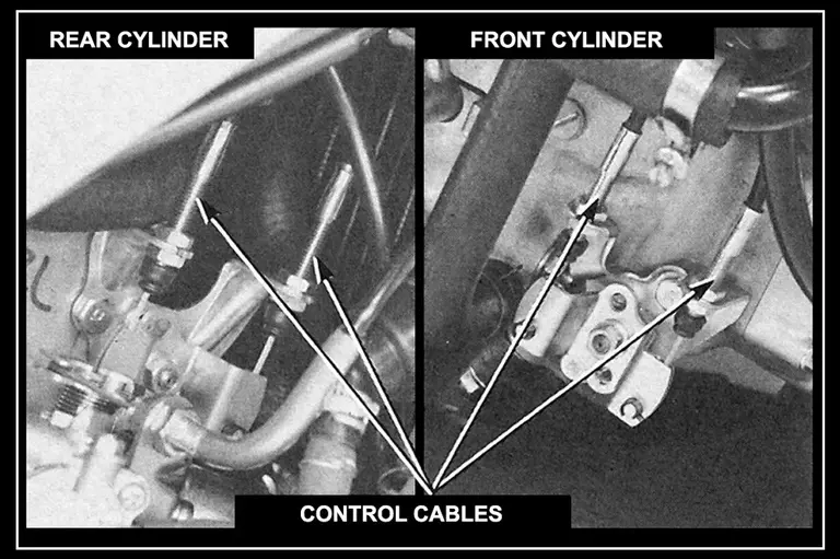
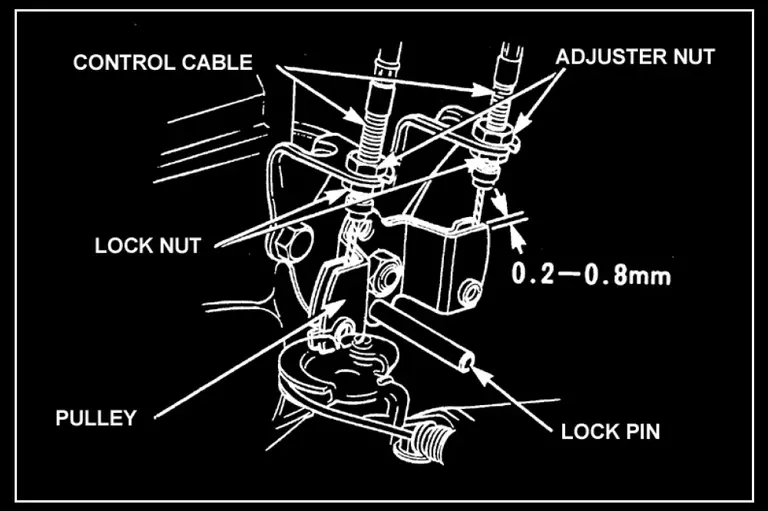
Loosen the cable locknuts, and slacken the actuator cables.
Insert knock pins into the RC Valve pulleys to lock them in the open position.
Adjust the cables so the pulleys have 0.5mm of free play. Tighten the locknuts securely.
Torque: 0.9 – 1.2 kg-m
Start the engine and slowly increase the engine speed to
around 2,000 rpm and check that the pulley moves clockwise
to a stop. Increase the engine speed to 3,000 rpm and check
that the pulley moves counter-clockwise to a stop.
1988 MC18-I
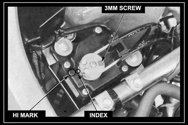
Start the engine, and slowly increase the engine speed. At approximately 2000rpm the RC Servo pulley will rotate to the “HI” position. Stop the engine with the kill switch. Using a 3mm screw, tighten the screw in the pulley to prevent the pulley from moving.
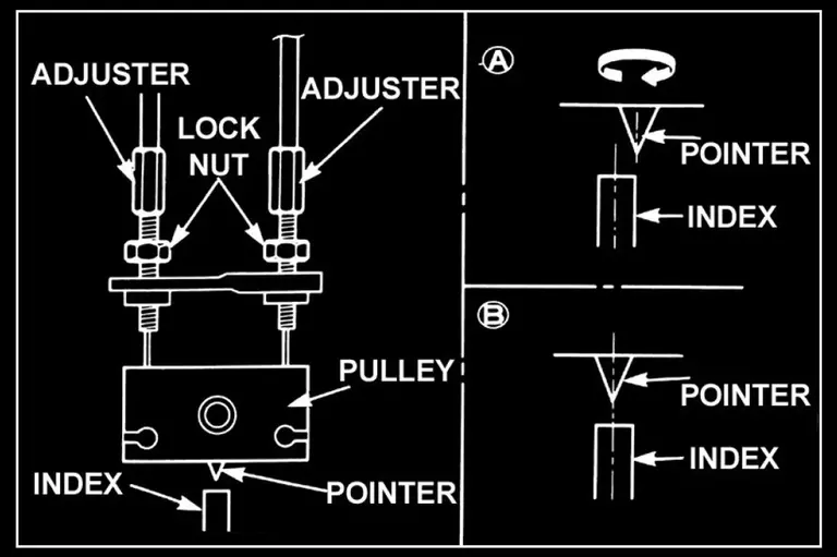
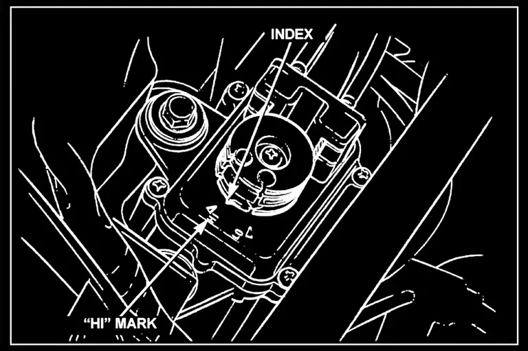
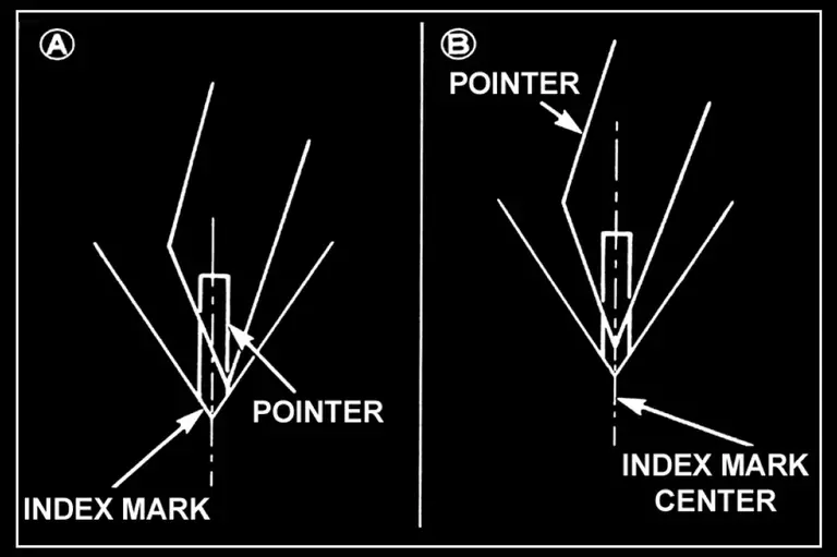
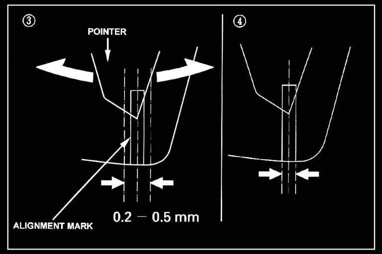
Loosen the lock nuts on both adjuster cables. Adjust the cables at the pulley end so the pointer aligns with the alignment mark on the back plate.
Turn the right adjuster cable so the pointer aligns with the right side of the adjustment mark as shown in (A).
Turn the left adjuster cable until the pointer aligns with the centre of the adjustment mark as shown in (B).
The pulley free play should be 0.5-1.0mm of free play. Adjust the left and right adjuster cables to allow for the proper free play.
Tighten the lock nuts on the left and right adjuster cables with the pointer aligned in the middle of the alignment mark as shown in the diagram.
1989 MC18-II
Start the engine, and slowly increase the engine speed. At approximately 2000rpm the RC Servo pulley will rotate to the “HI” position. Stop the engine with the kill switch. Using a 3mm screw, tighten the screw in the pulley to prevent the pulley from moving.
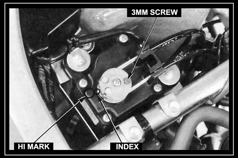
Loosen the cable locknuts, and slacken the actuator cables. Adjust the cables at the pulley end so the pointer aligns with the alignment mark on the back plate as shown in (B).
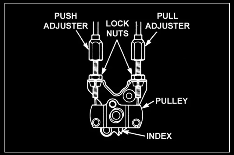
Turn the pull adjuster cable so the pointer aligns with the right side of the adjustment mark as shown in (A).
Turn the push adjuster cable till the pointer aligns with the centre of the adjustment mark as shown in (B).
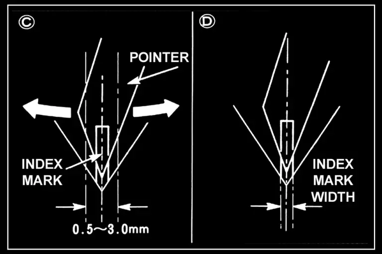
The pulley free play should be 0.5-3.0mm of free play as shown in (C). If the pulley free play is less then 0.5mm (cable is too tight) or over 3.0mm (cable too loose) follow the previous steps until properly adjusted
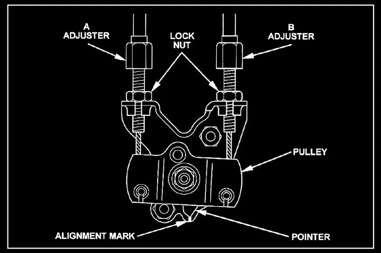
'90-'93 MC21
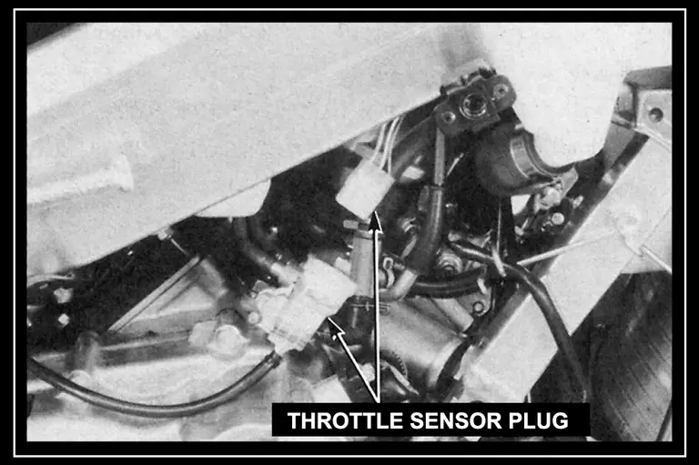
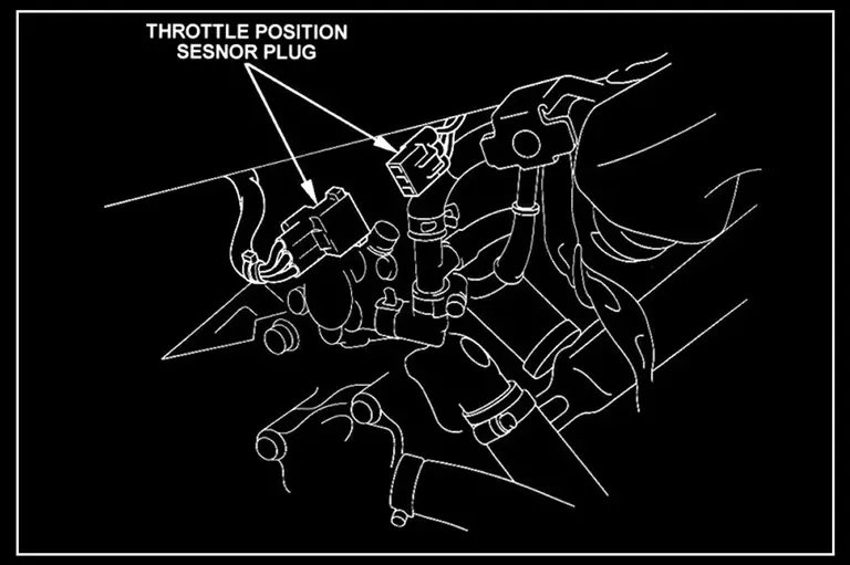
Turn the ignition off and switch the kill switch to the OFF position. Disconnect the Throttle Position Sensor plug. Turn the ignition switch ON, and check that the RC valve servo marker rotates to the “HI” position.
Loosen the lock nuts on the push/pull adjuster cables. Adjust the cables at the pulley end so the pointer aligns with the alignment mark on the back plate.
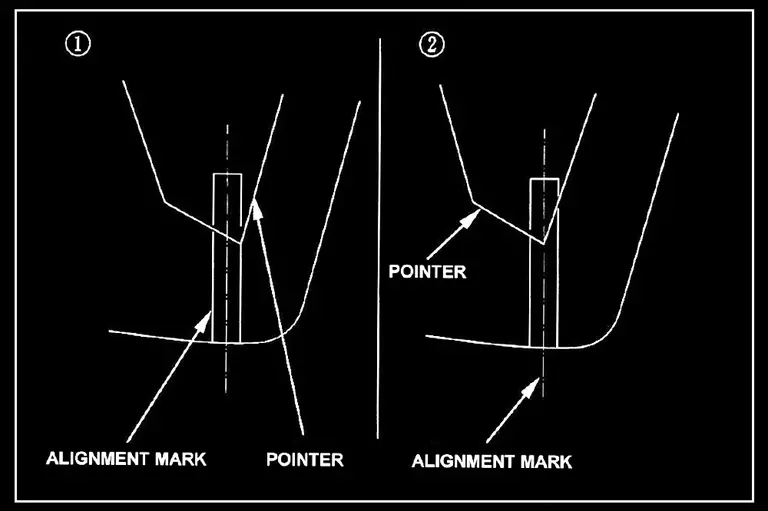
Turn the pull adjuster cable so the pointer aligns with the right side of the adjustment mark as shown in diagram 1.
Turn the push adjuster cable till the pointer aligns with the centre of the adjustment mark as shown in diagram 2.
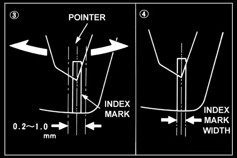
The pulley free play should be 0.2-1.0 mm as shown in diagram 3. Follow steps 1 and 2 until properly adjusted.
Tighten the lock nuts on the push and pull adjuster cables with the pointer aligned in the middle of the alignment mark as shown in diagram 4.
Adjust the other cylinder following steps 1, 2, 3 and 4.
Turn the kill switch to the OFF position. Connect the throttle position sensor connector/coupler.
'94-'96 MC28
With the PGM card removed, and the engine stop switch in the OFF position, disconnect the throttle position sensor plug. With the PGM card installed turn the engine stop switch to the RUN position.
The RC servo will rotate so the servo marker points to the open ‘Hi” position. Turn the engine stop switch to the OFF position.
Loosen the lock nuts on the A/B adjuster cables. Adjust the cables at the pulley end so the pointer aligns with the alignment mark on the back plate.
Turn the B adjuster cable so the pointer aligns with the right side of the adjustment mark as shown in diagram 1.
The pulley free play should be 0.2-0.5 mm as shown in diagram 3.
Adjust the A and B adjuster cables to allow for 0.2-0.5mm of free play. Follow steps 1 and 2 till properly adjusted.
Turn the A adjuster cable till the pointer aligns with the centre of the adjustment mark as shown in diagram 2.
Tighten the lock nuts on the A and B adjuster cables with the pointer aligned in the middle of the alignment mark as shown in diagram 4. Adjust the other cylinder following steps 1-4.
With the PGM card removed, and the engine stop switch in the OFF position, connect the throttle position sensor plug.
WARNING:
Correct adjustment of the RC Valve cables is critical to the health of the ’87-’88 RC servo controller and later PGM units.
Any strain arising from tight cables will cause the control circuit to overload and burn out the transistors, and potentially damage the RC servo motor too.